Determining application-specific peak power and energy requirements for ultra-low power processors Cherupalli et al., ASPLOS’17
We’re straying a little bit out of The Morning Paper comfort zone again this morning to look at one of the key hardware issues affecting the design of IoT devices: how much energy they use, and the related question of their peak power requirements. Why is this interesting? Firstly, there are way more ultra-low power (ULP) based devices out there than you might imagine. And secondly, since we can’t accurately gauge the energy and peak-power requirements, we tend to over provision, leading to larger, heavier systems than we could otherwise build. Cherupalli et al. demonstrate a technique that gives much more accurate estimates of peak power and energy requirements, with tighter bounds. By understanding these requirements in detail, the results can also be used to guide optimisations that reduce power usage. We’ll get to all that soon, but first we need to dig a little deeper into the world of ULP devices.
The world of ultra-low power processors
What’s the most widely deployed type of processor in the world? It’s not the processors that power our PCs and laptops of course, nor is it even the processors you’ll find in mobile phones.
Ultra-low power (ULP) processors have rapidly become the most abundant type of processor in production today.
This is driven by new and emerging power- and energy- constrained applications such as IoT, wearables, implantables (I didn’t know that was a word!), and sensor networks. ULPs are projected to continue being the most widely deployed type of processor in the future.
… applications will continue to rely on simple single-core ultra-low power processors, powered by batteries and energy harvesting, and will have even tighter peak power and energy constraints than the ULP systems of today.
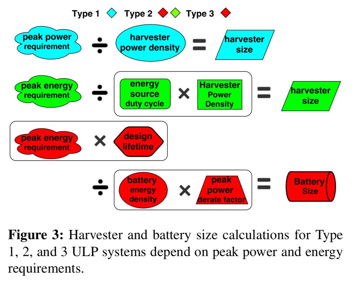
In the world of ULPs, power is everything. There are three basic types of systems depending on the source(s) of power:
- Type 1 systems are powered directly by energy harvesting (e.g., a solar cell)
- Type 2 systems are powered by a battery, which in turn is charged via energy harvesting
- Type 3 systems just have a battery
It’s the size of the energy harvesting and/or energy storage (battery) components that ultimately determine the form factor, size, and weight of an ULP-based device. For example:
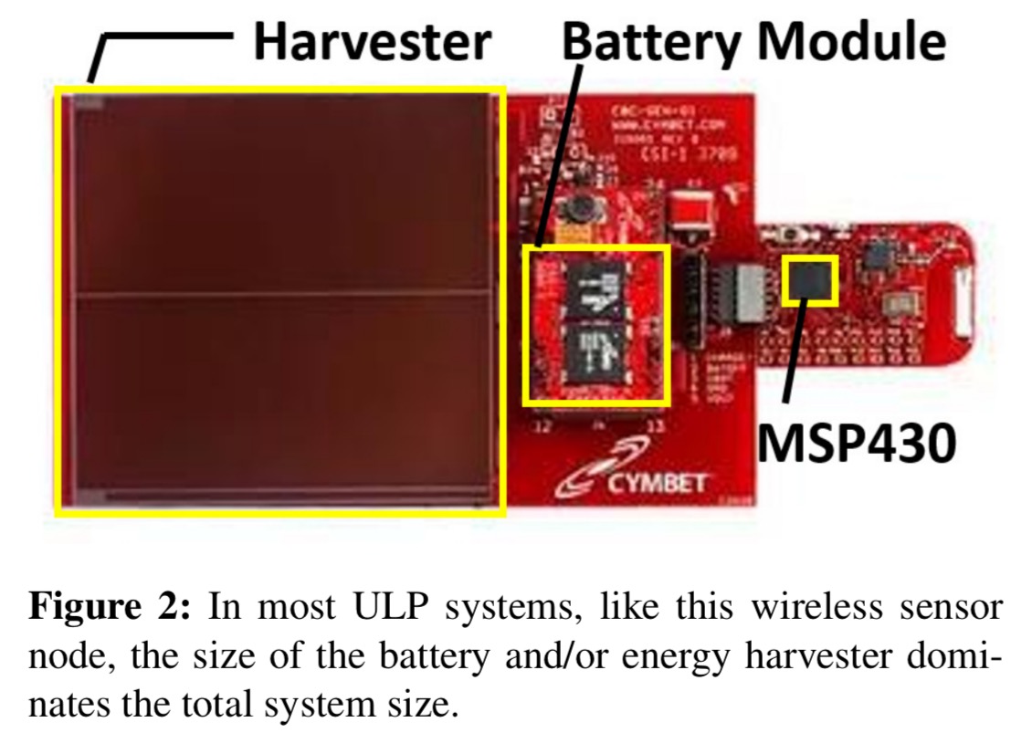
Going one step further, since the energy harvesting and storage requirements of a ULP system are determined by its power and energy requirements, the peak power and energy requirements of a ULP system are the primary factors that determine critical system characteristics such as size, weight, cost, and lifetime
Peak power and energy consumption impact harvester and battery size calculations in different ways depending on the type of device:
Current approaches for determining peak power and energy
There are three basic approaches for determining the peak power and energy requirements of a ULP processor for a given application.
- For a very conservative upper bound, you can just look at the data sheets for the processor, which tell you the peak power than can be consumed by the hardware.
- You can run a stressmark: an application that attempts to activate the hardware in a way that maximises peak power or energy. “A stressmark may be less conservative than a design specification, since it may not be possible for an application to exercise all parts of the hardware at once.”
- You can perform application profiling on the processor by measuring power consumption while running the target application on the hardware.
A bit more work, but #3 sounds like an obviously good idea. So what’s the catch?
… since profiling is performed with specific input sets under specific operating conditions, peak power or energy bounds determined by profiling might be exceeded during operation if application inputs or system operating conditions are different than profiling.
Things tend not to work out well if a processor does try to operate outside of the peak power and energy bounds available to it, so best practice is to add a guardband (power buffer) to any profiling-based results. A typical guardbanding factor might be 33%. In other words, take the profiling results, add 33%, and provision for that.
Input-independent peak power and energy profiling
Since the peak power and energy requirements of an application can vary based on application inputs, a technique that determines application-specific peak power requirements must bound peak power for all possible inputs. Exhaustive profiling for all possible inputs is not possible for most applications, so we have created a novel approach for activity analysis that uses unknown logic values (Xs) for inputs to efficiently characterize activity for all possible inputs with minimum simulation effort.
The core idea is to run a symbolic simulation of an application binary on ‘the gate-level netlist of a processor.’ (What is a netlist?). Most ULP systems tend to have simple processors and applications, making simulation feasible. For example, even the most complex benchmark analysed in the paper completed full simulation in 2 hours.
During the simulation, a special ‘X’ value is propagated for all signal values that can’t be constrained based on the application. We start with all gates and memory locations not explicitly loaded with the binary set to X. Any input values during simulation are also set to X.
As simulation progresses, the simulator dynamically constructs an execution tree describing all possible execution paths through the application. If an X symbol propagates to the inputs of the program counter (PC) during simulation, indicating an input-dependent control sequence, a branch is created in the execution tree. Normally, the simulator pushes the state corresponding to one execution path onto a stack for later analysis and continues down the other path.
At the end of this process we know the activity of each gate at each point in the execution tree. A gate that is not marked as toggled (0 to 1, or 1 to 0) at a particular location in the tree can never be toggled at that location in the application. We can use this knowledge encoded in the execution tree to generate peak power requirements as follows:
- Concatenate all of the execution paths into a single execution trace.
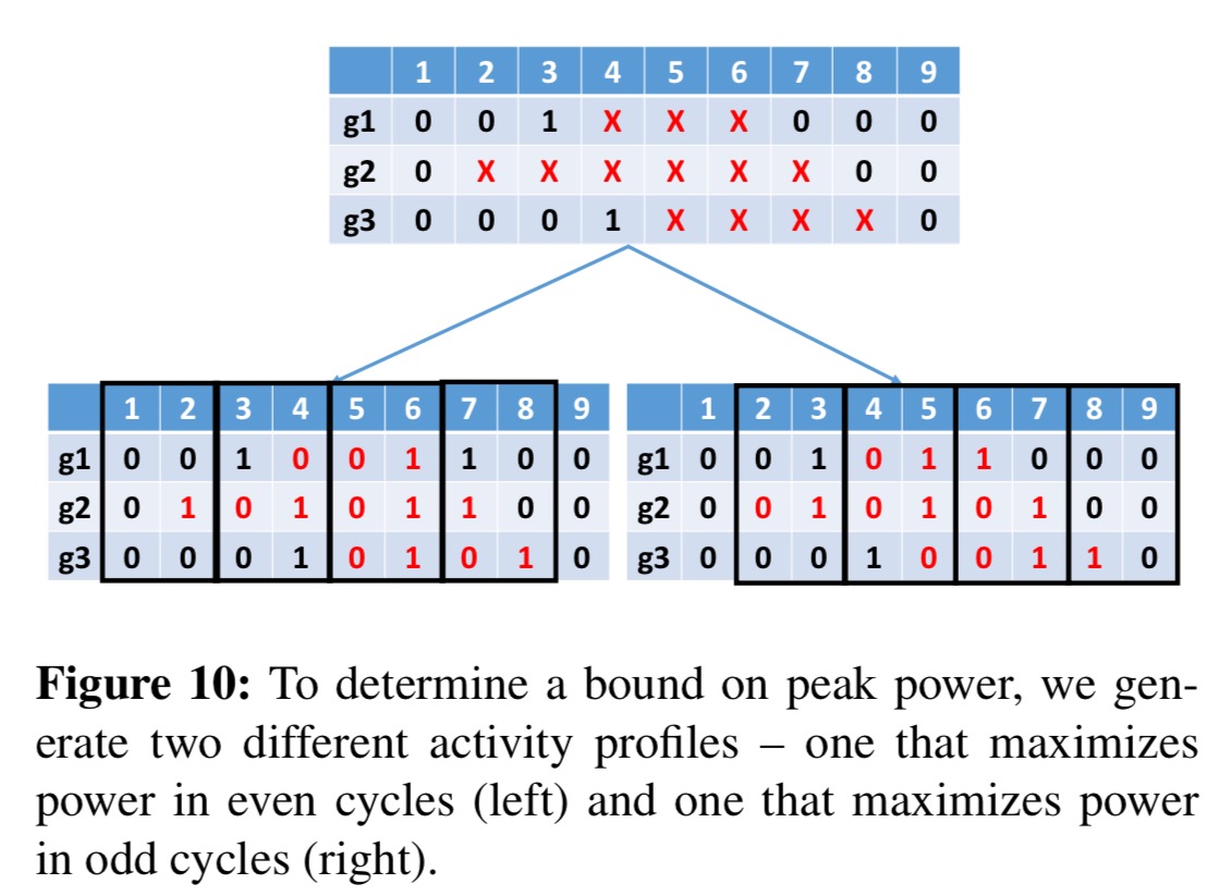
- Assign all of the Xs in the trace in such a way that power for each cycle is maximised. Power is maximised when a gate toggles, but a transition requires two cycles: one to prepare and one to make the transition. Since we don’t know the best way to align transitions with cycles, two separate value change dump (VCD) files are produced: one that maximises power in all even cycles, and one that maximises power in odd cycles.
- Combine the even and odd power traces into a single peak power trace by taking power values from even cycles in the even trace, and odd cycles in the odd trace.
- The peak power requirement of the application is the maximum power cycle value found in the peak power trace.
The peak power trace can be used to generate peak energy requirements.
… the peak energy of an application is bounded by the execution path with the highest sum of per-cycle peak power multiplied by the clock period.
When making this calculation, for input-dependent branches the algorithm always take the most expensive one. For loops where the maximum number of iterations can be determined simply take the energy for one iteration and multiply it by that max. “If neither is possible, it may not be possible to compute the peak energy of the application; however, this is uncommon in embedded applications.”
Results
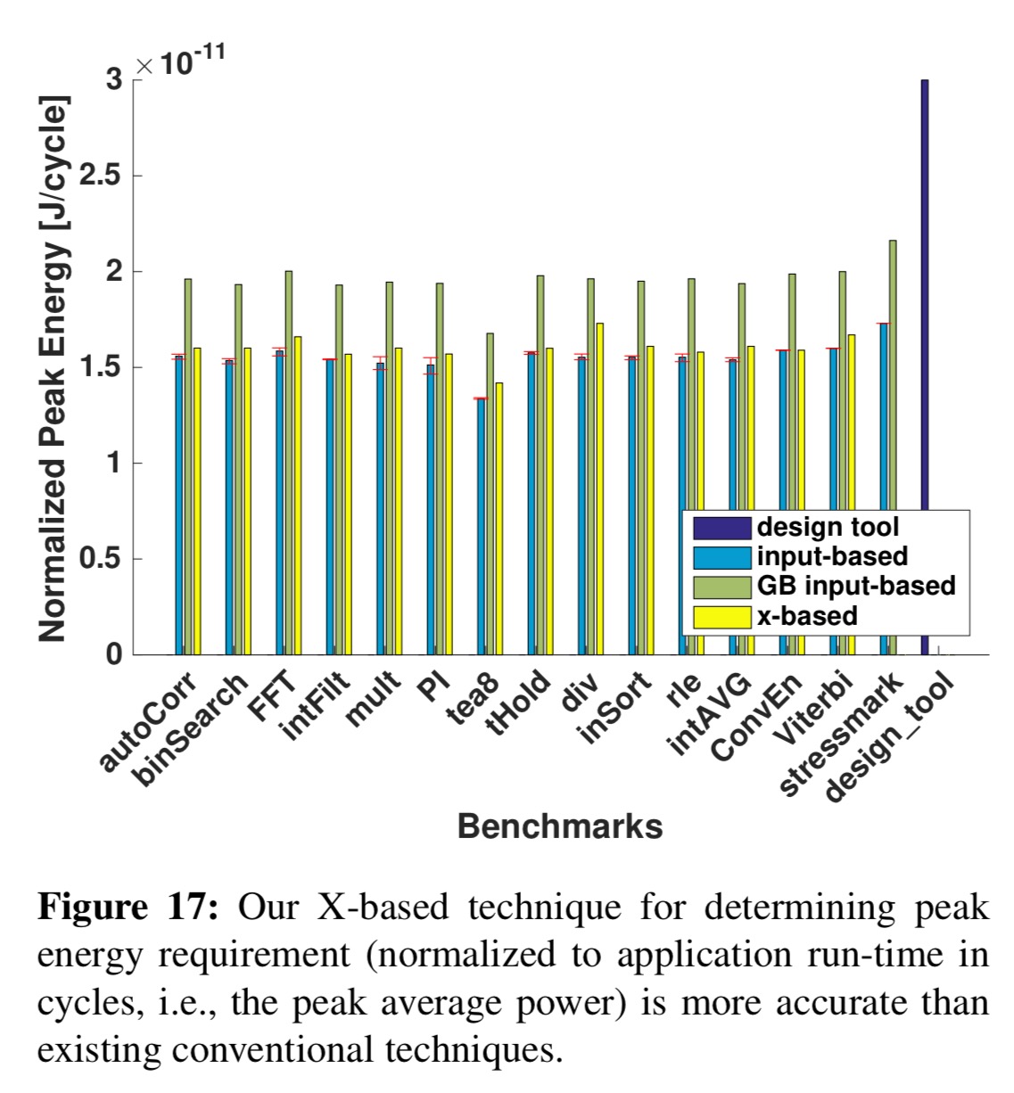
The chart below shows the peak power requirements determined using the above process as compared to the conventional techniques for determining peak power.
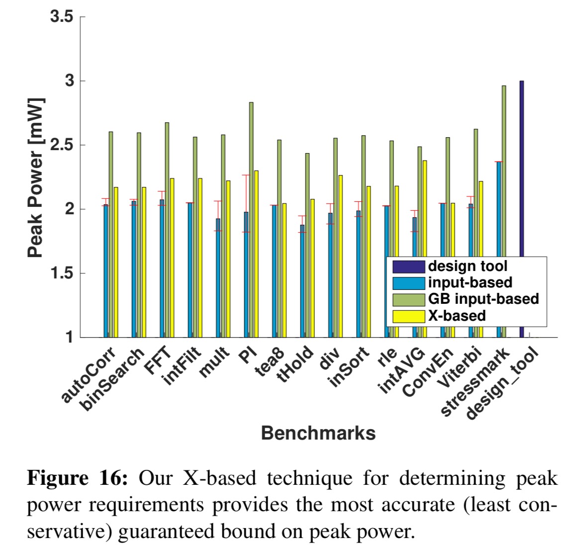
By accounting for all possible inputs using symbolic simulation, our technique can bound peak power and energy for all possible application executions without guardbanding. The peak power requirements reported by our technique are 15% lower than guardbanded application-specific requirements, 26% lower than guardbanded stressmark-based requirements, and 27% lower than design specification-based requirements, on average.
Here are the results of the peak energy calculations:
… the peak energy requirements reported by our technique are 17% lower than guardbanded application-specific requirements, 26% lower than guardbanded stressmark-based requirements, and 47% lower than design specification-based requirements, on average.
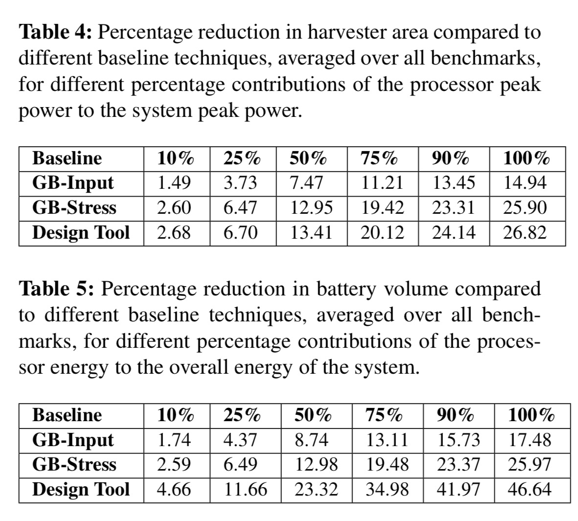
The following tables show how this would translate into harvester area and battery volume reductions.
Optimising peak power guided by profile results
The technique can also be used to guide application-based optimisation by analysing the processor’s behaviour during the cycles of peak power consumption. Three different optimisations can then be applied as appropriate:
- Reduce a complex instruction that induces a lot of activity in one cycle, with a sequence of simpler instructions, thus spreading out the activity over several cycles.
- Delay the activation of one or more modules, previously activated in a peak cycle, until a later cycle.
- Avoid the multiplier being active simultaneously with the processor core by inserting a NOP into the pipeline during the cycle in which the multiplier is active.
Taking combined figures across the benchmarks in the paper, these produced peak power reductions of up to 10% (5% on average), with up to 34% (18% on average) reduction in peak power dynamic range.

So, you get peak power for the processor, but not for they system. The battery has to supply the whole system, and the processor is only one piece of that puzzle.