Modelling the ARM v8 Architecture, Operationally: Concurrency and ISA – Flur et al. 2016
You can take all the care you like specifying, implementing, and verifying your software, but if the hardware it runs on is ill-defined at the end of the day you’re just building on sand. In today’s paper choice, Flur et al. set out to resolve ambiguities in the behaviour of the ARM v8 architecture. Along the way, you get some great insights into just how complex modern processors are.
The [ARM] architecture defines the properties on which software can rely on, identifying an envelope of behaviour that all these processors are supposed to conform to. It is thus a central interface in the industry, between those hardware vendors and software developers…. However, exactly what behaviour is and is not allowed by the architecture is not always clear, especially when it comes to the concurrency behaviour of ARM multiprocessors. The architecture aims to be rather loose, to not over-constrain the hardware microarchitectural design choices of all those different vendors, and to permit optimised implementations with high performance and low power consumption. To this end, it adopts a relaxed memory model, allowing some effects of out-of-order and non-multi-copy-atomic implementations to be programmer-visible. But it describes that in prose, which, as one might expect, leaves many open questions.
The authors set out to create mathematically rigorous models of the ARM architectural intent – a level of preciseness which has not previously been available, either in documentation or indeed internally within ARM. Collaboration with the ARM architects to help clarify intended behaviours was essential to the project, and this requirement helped to shape the overall approach. To make the model accessible to hardware architects and to facilitate discussion,
…we first develop a concurrency model with a microarchitectural flavour, abstracting from many hardware implementation concerns but still close to hardware-designer intuition, so that it can be clearly (albeit necessarily informally) related to the processor designs they have in mind, and be tested against their extensional behaviour.
This lower-level model is called the Flowing Model, and it captures the allowed behaviours as read requests, write requests, and barriers flow explicitly through a hierarchical storage system. The Flowing Model is great for discussion with the hardware designers, but not an ideal basis for an architectural specification or programming model. A second model is therefore developed, the Partial-Order Propagation (POP) model, which abstracts from the storage hierarchy and treats all hardware threads symmetrically. This higher-order model is proved sound with respect to the Flowing Model.
Both models have been discussed in detail with senior ARM staff, resolving many subtle questions about the architecture.
Understanding the concurrency model is very important, but not by itself sufficient. It is also necessary to define semantics for the Instruction Set Architecture (ISA):
The ARM architecture describes the sequential behaviour of the ISA reasonably precisely, in a proprietary pseudocode language; the problems here are (1) dealing with the mass of detail involved, and (2) integrating these sequential descriptions into the concurrent semantics. One cannot simply treat each instruction as an atomic transaction, or interleave their pseudocode. Previous work on relaxed-memory semantics has not really addressed this issue, either avoiding it entirely or defining semantics for a small ad hoc fragment of the ISA.
As you might expect, there is an immense amount of detail in this paper. Something that I found very helpful is the online web interface that animates the models and lets you explore the behaviour of both the flowing model and the POP model interactively: http://www.cl.cam.ac.uk/~sf502/popl16/help.html.
The Flowing Model
Modern high-end processors are astonishingly complex. The pipeline of an ARM Cortex-A57 core can have up to 128 instructions in flight simultaneously, with each instruction broken down into micro-operations that are dispatched to multiple arithmetic, branch, floating-point, and load/store execution units. Shadow registers and register renaming are used to prevent the number of architected registers being a bottleneck.
The flowing model is in three parts: an instruction semantics defines the behaviour of each operation in isolation – the steps of the semantics are micro-operations abstracting from the actual hardware micro-operations performed by the arithmetic units etc.. The thread subsystem models the execution of instructions in a single core (or hardware thread).
This abstracts from the out-of-order dispatch and control logic, the register renaming, the load/store queues, and the local (L1) cache of the core, modelling all that with a simple tree of instruction instances. Some of these may be finished, while others may be executing out-of-order or speculatively, after a conditional branch (the forks) which is not yet resolved. The ISA model generates events, principally: register-read, register-write, memory-read, memory-write and barrier, which are used by the thread-subsystem; some involve instruction-state continuations, e.g. to record an instruction state which is awaiting the result of a memory read.
The storage subsystem abstracts from the interconnect and shared cache levels in the microarchitecture. It receives memory read, write, and barrier requests from the thread and replies with read responses containing the write to be read from. These requests are modeled as they flow from hardware threads through cache levels and to the memory.
The ARM architecture is not multi-copy atomic: a write by one hardware thread can become visible to some other threads before becoming visible to all of them. Microarchitecturally, this behaviour can arise from multi-level cache and core clustering. Two cores that share a cache level that is not shared with a third core can observe each other’s memory accesses before the third core does. ARM architects reason about the behaviour of this by abstracting it to a tree-shaped topology of queues in which requests “flow”, starting from the entry point of the issuing thread through join points until they reach main memory. On their way to main memory some requests might bypass others subject to reordering conditions. In this abstraction, read requests do not need to travel all the way to main memory to get satisfied: if a read request encounters a write to the same address, a read response can be immediately sent to the issuing thread of the read request. This abstraction is the inspiration behind the Flowing storage subsystem.
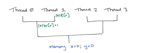
Let’s look at an example of the flowing model in action. Many different processor topologies are possible. Consider one in which the pair of threads 0,1 both share a queue, and the pair of threads 2,3 share another queue. We join the action when the memory contains (x=0;y=0), and threads 0, 1, and 2 are executing instructions as follows:
Thread 0:
  (a) W[x] = 1

Thread 1:
  (b) val = R[x]
  (c) W[y] = val

Thread 2:
  (d) val = R[y]
  (e) val' = R[x]
The write (b) and read (e) in threads 1 and 2 respectively are address dependent on the earlier read in the same thread (and so can’t be re-ordered with respect to it). This Tutorial Introduction to the ARM and Power Relaxed Memory Models provides helpful background.
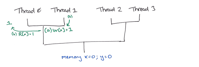
Consider a point at which write (a) has ‘flowed down’ past the first join point, with the read (b) still above it:
The read request (b) may then flow down another step, where it can be satisfied by (a).
This resolves the address dependency to write (c) which can flow down to the same point.
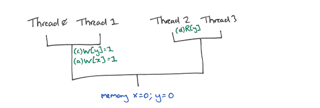
(c) and (a) can now be reordered, and (c) may flow down to satisfy the read (d) in thread 2.
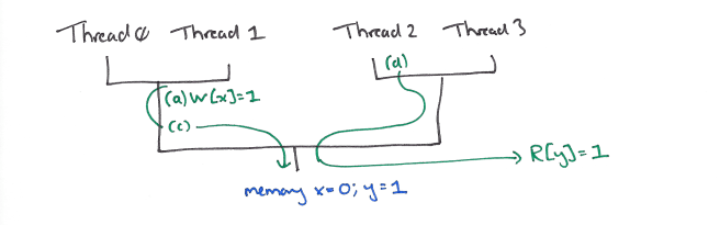
This in turn resolves the address dependency to read (e), which can flow down and be satisfied by the value x=0 in main memory before the write (a) reaches memory.
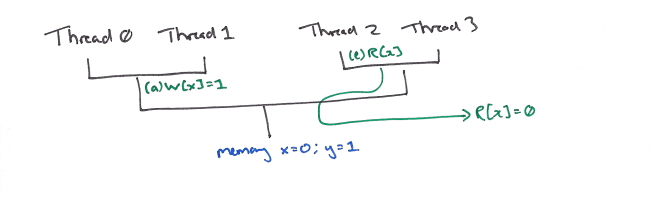
Finally (a) may then reach memory where x will be updated to the value 1.
(Play with this example in the flow model in the interactive browser: click on ‘Select ARM Test’ and choose WRC+addrs in the TUTO section, then click ‘Run Interactive.’ Full instructions for using the web tools are here. ).
See §7 in the paper for the full details.
The asymmetry between hardware threads is uncomfortable from an architectural point of view (programmers will typically not know the assignment of software threads to particular hardware threads, and should not write code where the correctness depends on that assignment); it is exactly that asymmetry that our POP model will abstract from.
The Partial-Order Propagation Model
The POP model reuses the instruction semantics and thread subsystem from the Flowing Model, and replaces the storage subsystem model with a more abstract model.
The purpose of the queues in the Flowing storage subsystem is to maintain order between requests, relaxing it subject to the reordering condition. The topology, on the other hand, determines the order in which a request becomes visible to the threads. Consider for example the write (a) W[x]=1 in the first storage subsystem state diagram (above) for WRC+addrs. It is visible to threads 0 and 1, as a read request from each of these threads can potentially flow and encounter (a), but it is not visible to threads 2 and 3, as a read request issued by those would flow all the way to memory without encountering (a). In the POP model we make these two notions explicit. Instead of the queues enforcing an implicit order we record an order (as a graph) over all requests, and instead of letting a fixed topology determine the order in which a request becomes visible, we record for each thread a set of requests that have become visible to it, and we allow requests to be added to these sets (subject to conditions over its place in the order).
See §8 for a detailed description.
(Play with this example in the POP model in the interactive browser using the same options as before).
ISA Model
The ISA model is built using a DSL for ISA description called Sail:
The ARM ARM has 224 application-level non-FP/SIMD instructions, counting subsections of Chapter C6 A64 Base Instruction Descriptions (each of which defines one instruction, some times with several variants). Of these 224, we support all except 21 (and aspects of 4 more), relating to exceptions, debug, system-mode, and load-non-temporal-pair…. Hardware vendors differ widely in the level of detail and rigor of their instruction descriptions. The ARM ARM is relatively good in these respects: the pseudocode used is reasonably complete and close to something that could be executed, at least for sequential code (Shi et al. build a simulator based on pseudocode extracted from an ARMv7 pdf [25]). We therefore want to follow it closely, both to avoid introducing errors and to keep our definitions readable by engineers who are already familiar with the ARM ARM. Sail
is designed with this in mind, and our instruction descriptions can often be line-for-line identical to those of the ARM ARM.
The dynamic semantics of Sail integrate with the thread subsystem semantics.

One thought on “Modelling the ARM v8 Architecture, Operationally: Concurrency and ISA”
Comments are closed.