Clay codes: moulding MDS codes to yield an MSR code Vajha et al., FAST’18
As we know, storage fails (or the nodes to which it is directly attached, which amounts to pretty much the same thing). Assuming we can detect the failure, we need to recover from it. In order to be able to recover, we need to have redundant information stored outside of the failure zone. There are a number of factors to consider in any scheme, for example:
- What is the storage overhead? (E.g., in a straightforward n=3 replication scheme, we need 3x the original storage!).
- How long does it take to recover missing data? (Reading from disk, transferring over the network, imputing the missing bytes if using a coding scheme).
- What resources does it consume during recovery? (E.g., does it saturate network bandwidth?)
In order to be failure tolerant, data centers have increasingly started to adopt erasure codes in place of replication. A class of erasure codes known as maximum distance separable (MDS) codes offer the same level of failure tolerance as replication codes with minimal storage overhead. For example, Facebook reported reduced storage overhead of 1.4x by using Reed-Solomon codes, a popular class of MDS codes, as opposed to the storage overhead of 3x incurred in triple replication.
(See ‘f4: Facebook’s warm blob storage system,’ and ‘A hitchhiker’s guide to fast and efficient data reconstruction in erasure coded data centers’).
A class of erasure codes known as minimum storage regenerating (MSR) codes offer the advantaged of MDS codes, but with lesser repair bandwidth (the Achilles’ heel of MDS). Until Ye and Barg though, no-one had shown a theoretical construction of an MSR code meeting all the requirements of real-world systems.
This paper presents Clay codes that extend the theoretical construction presented in Ye and Barg, with practical considerations. We implement Clay and make it available as open-source under LGPL.
Clay (Coupled Layer) codes have a number of properties that make them attractive:
- Low storage overhead
- Optimal repair bandwidth
- Optimal disk I/O
- Optimal sub-packetization level (we’ll look at what that is later)
- Uniform repair performance of data and parity nodes
- Support for both single and multiple-node repairs, while permitting faster and more efficient repair.
A natural question to ask is if these impressive theoretical credentials of the Clay code result in matching practical performance. We answer this question in the affirmative here by studying the real-world performance of the Clay code in at Ceph setting, with respect to network traffic for repair, disk I/O during repair, repair time, and degraded I/O performance.
A Clay code with storage overhead 1.25x reduced repair network traffic, disk read, and repair times by 2.9x, 3.4x, and 3x respectively. Could we be about to see an industry shift towards adoption of Clay codes? The paper describes the integration into Ceph and the subsequent evaluation, but I’m going to focus my limited space here on trying to explain how Clay codes work. First, a little background on erasure codes, MDS, and MSR.
Erasure code preliminaries
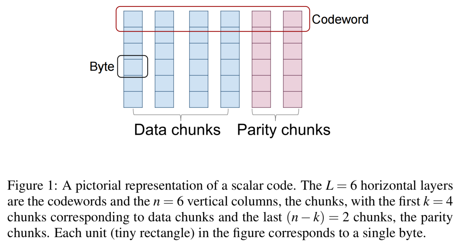
Erasure codes are an alternative to replication for ensuring failure tolerance in data storage. In an [n,k] erasure-coded system, data pertaining to an object is first divided into k data chunk and then encoded to obtain m = n-k parity chunks.
After encoding, the n coded chunks (data + parity) are stored on n distinct nodes. In scalar codes one byte from each of the k data chunks is picked, and the k bytes are linearly combined in m different ways, to obtain m parity bytes. The resulting set of n = k + m bytes is called a codeword.
In vector codes, instead of working with a single byte at a time from each data chunk, we work with ordered collections of 

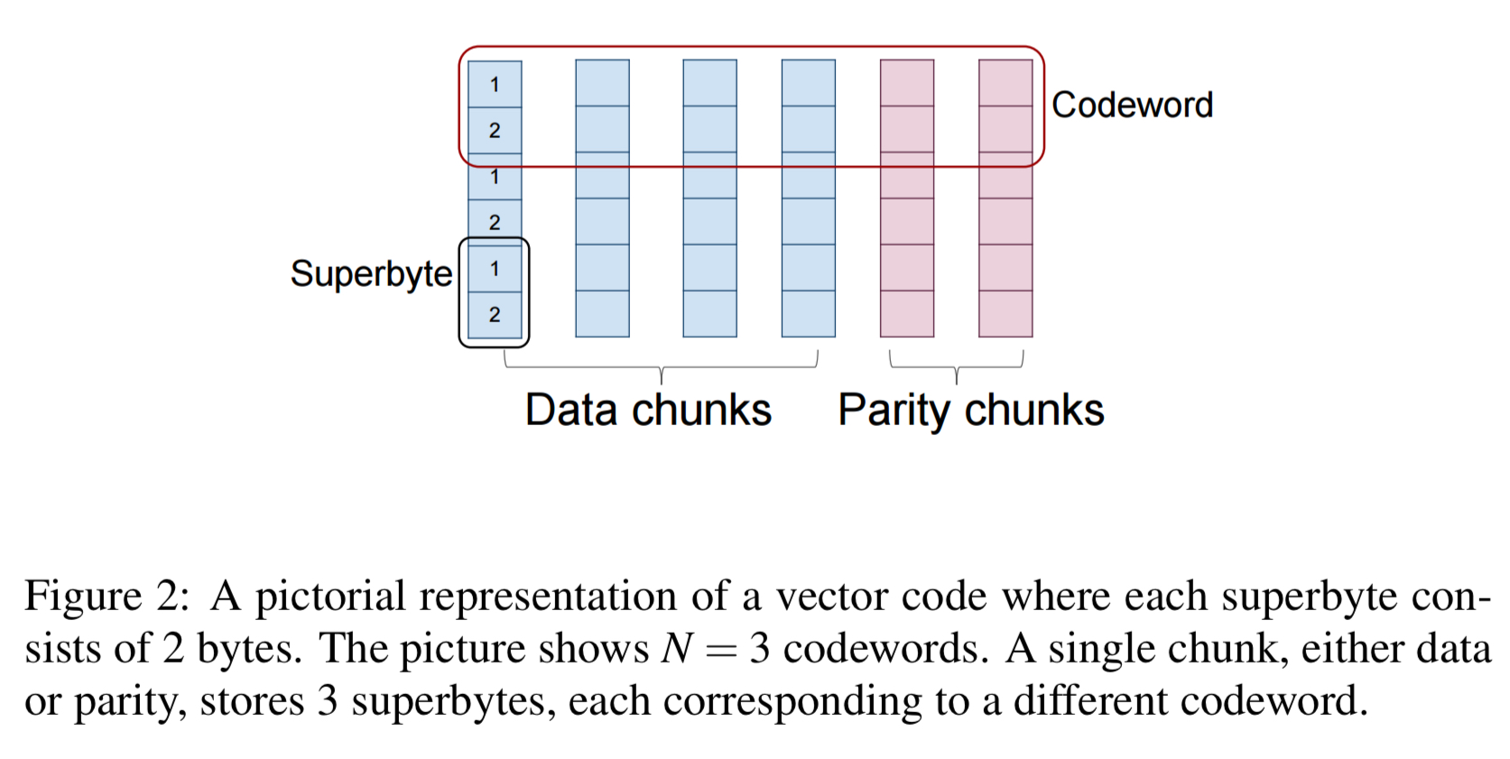
If the number of bytes in a data chunk is L, then we will have 
The sub-class of (n,k) erasure codes, either scalar or vector, have the property that they can recovery from the failure of any (n-k) nodes are called MDS (maximum distance separable) codes. For a fixed k, these codes have the smallest storage overhead n/k among any of the erasure codes that can recover from a failure of a fixed number of n-k nodes.
Reed-Solomon encoding is a well-known example.
In general, MDS codes can generate a substantial amount of network traffic during node repair operations. MSR (minimum storage regenerating) codes are a subclass of vector-based MDS codes that have the smallest possible repair bandwidth. To restore a failed node under MSR it is necessary to contact an arbitrarily chosen subset of d helper nodes (d is a design parameter between k and n-1). From each of these nodes, ")
.. the larger the number (n-k) of parity chunks, the greater the reduction in repair traffic.
Clay codes
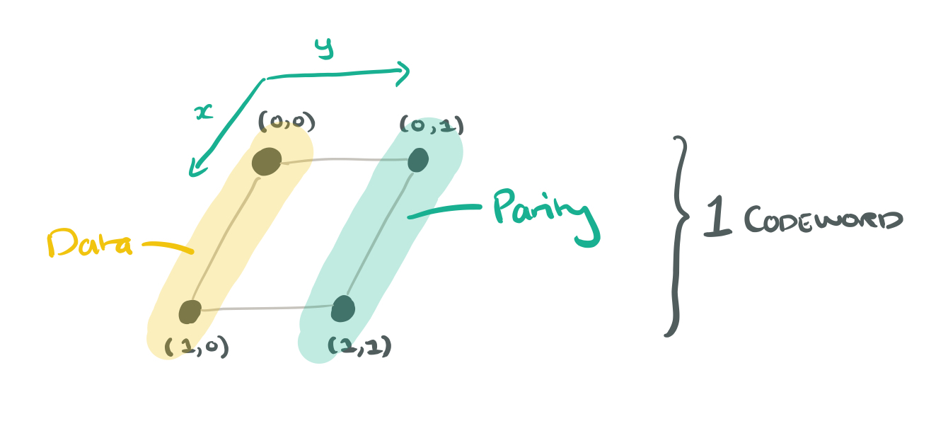
A Clay code is an MSR code with a number of desirable properties as outlined earlier. We’ll build up to the full Clay coding system in stages. Consider a Clay code with parameters:
- (n = 4, k=2) : 4 nodes in total, of which 2 are data nodes and 2 are parity nodes
- d = 3 : we contact 3 helpers during repair
: 4 bytes in a superbyte, 2 bytes required to be downloaded from each of the helper nodes during repair.
- M = 8 : 8 data bytes in total in a codeword (
)
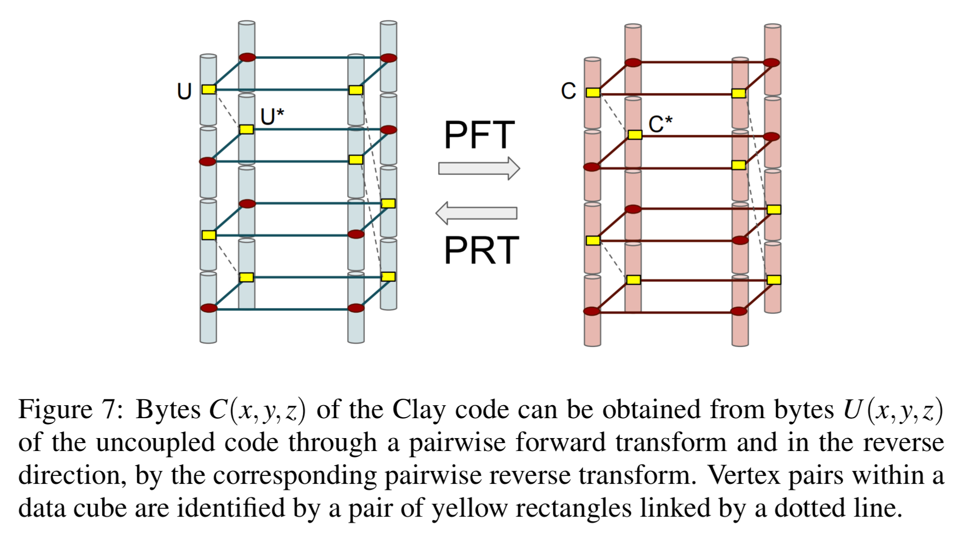
Take the n = 4 nodes, and arrange them in a grid indexed by ")
Now suppose we have four codewords. We could store 4 bytes on each node now, giving an uncoupled code. Each layer still stores a single codeword, and the parameter z is used to index codewords. Visually it looks like a data cube where the columns are superbytes and the layers are codewords:
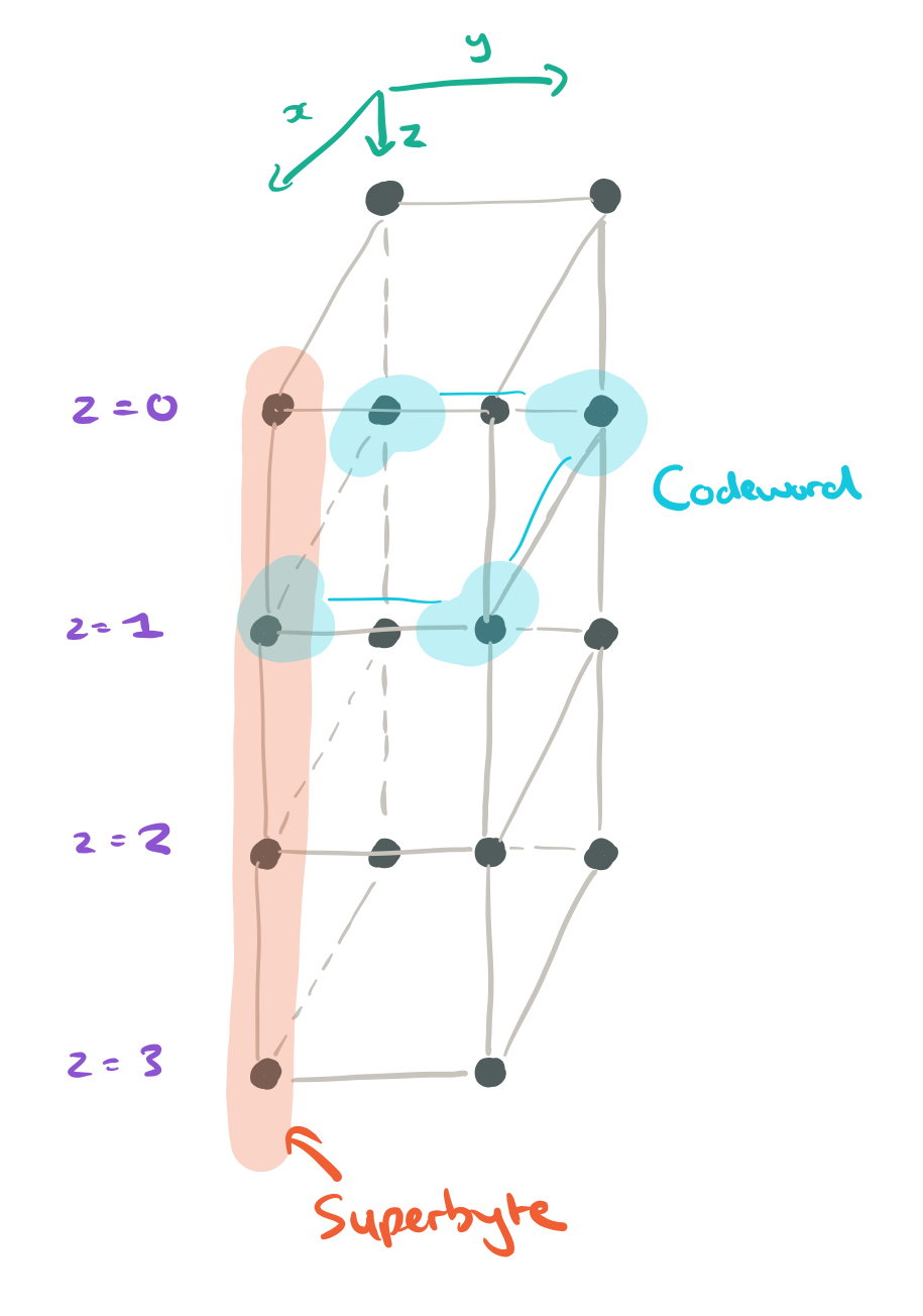
Now we can begin to turn this uncoupled starting point into a coupled-layer, or Clay, code. The first thing we need to do is identify nodes that we’re going to pair, and nodes that we’ll leave unpaired. There’s a fairly odd way of doing this (at least I don’t find it intuitive), but let’s roll with it…
- Take the z values (0,1,2,3) and represent them in binary as the digits
(so e.g. z=2 will be 1,0)
- Take the (x,y) coordinates of a node, and colour it red if
(i.e., use the value of y to index into the z digits, and check to see whether the value you find there equals x).
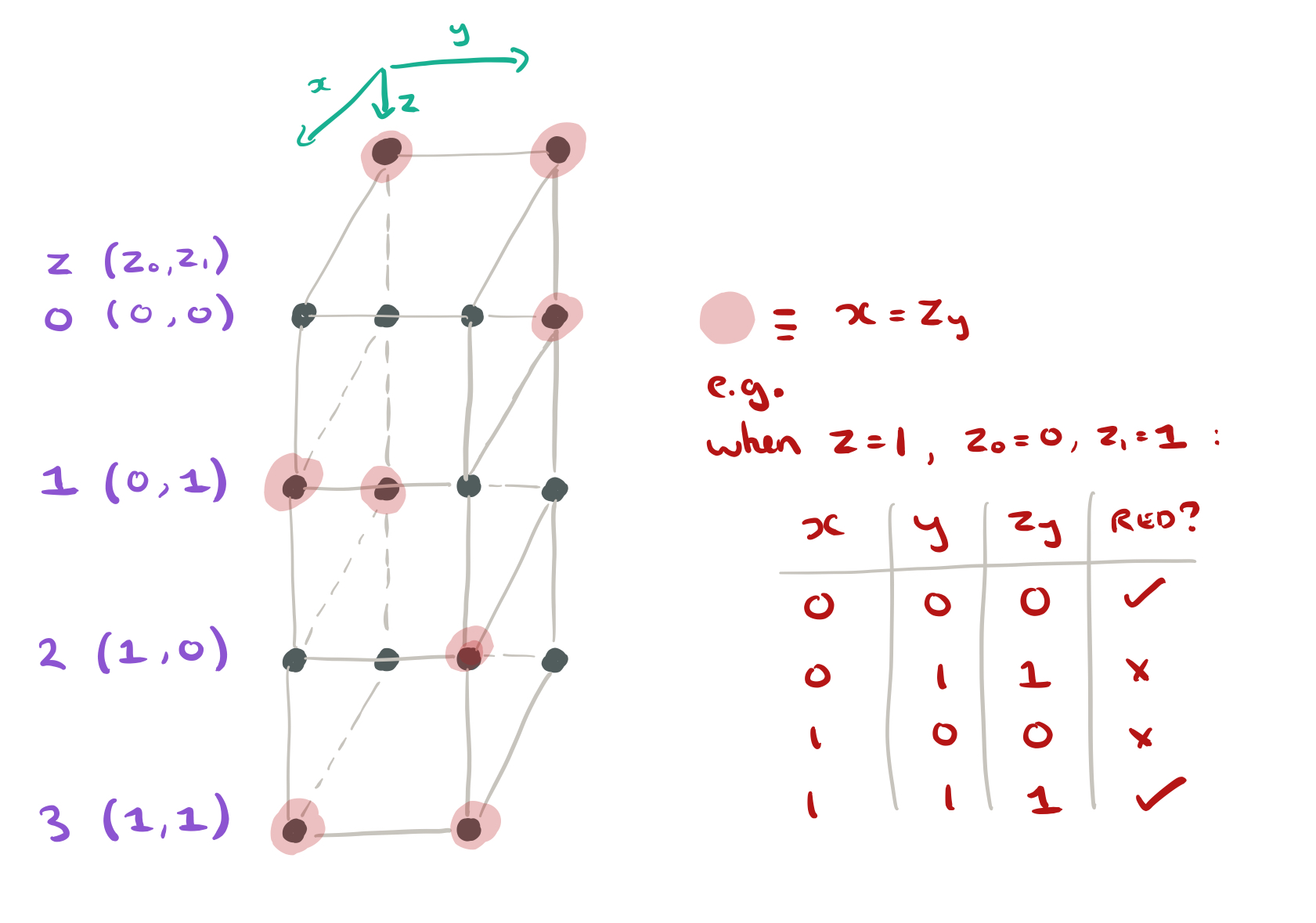
Red nodes will be unpaired. Let ")
The Clay code associates a byte C(p) with each vertex p of the data cube just as does the uncoupled code U. The bytes U(p) and C(p) are related in a simple manner. If p corresponds to an unpaired (and hence colored in red) vertex, we simply set C(p) = U(p)…
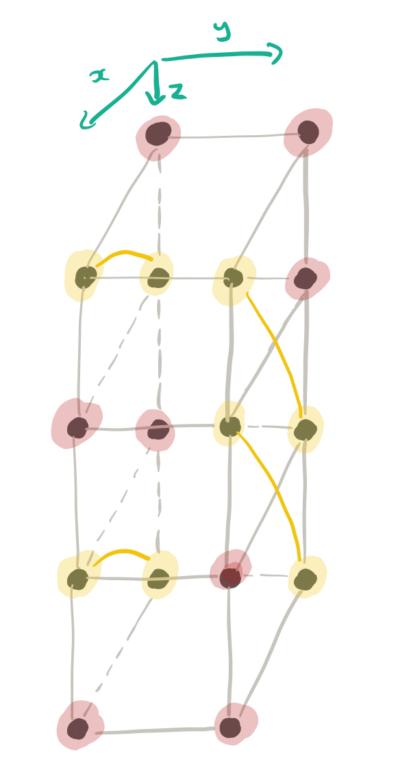
The remaining nodes are paired off, based on shared y-values, becoming companion vertices.
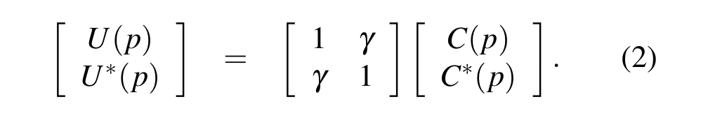
If (p,p*) are a pair of companion vertices,
,
,
and
,
are related by the following pairwise forward transform (PFT):
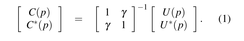
To go in the other direction, we can use a pairwise reverse transform (PRT):
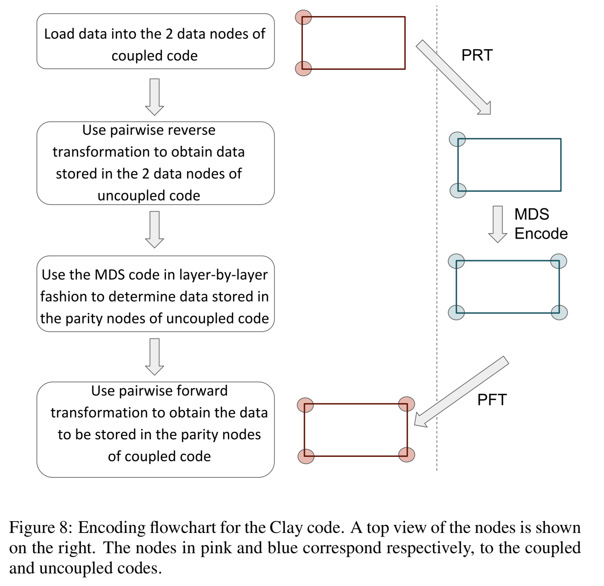
Finally, given this setup, Clay encoding proceeds as follows:
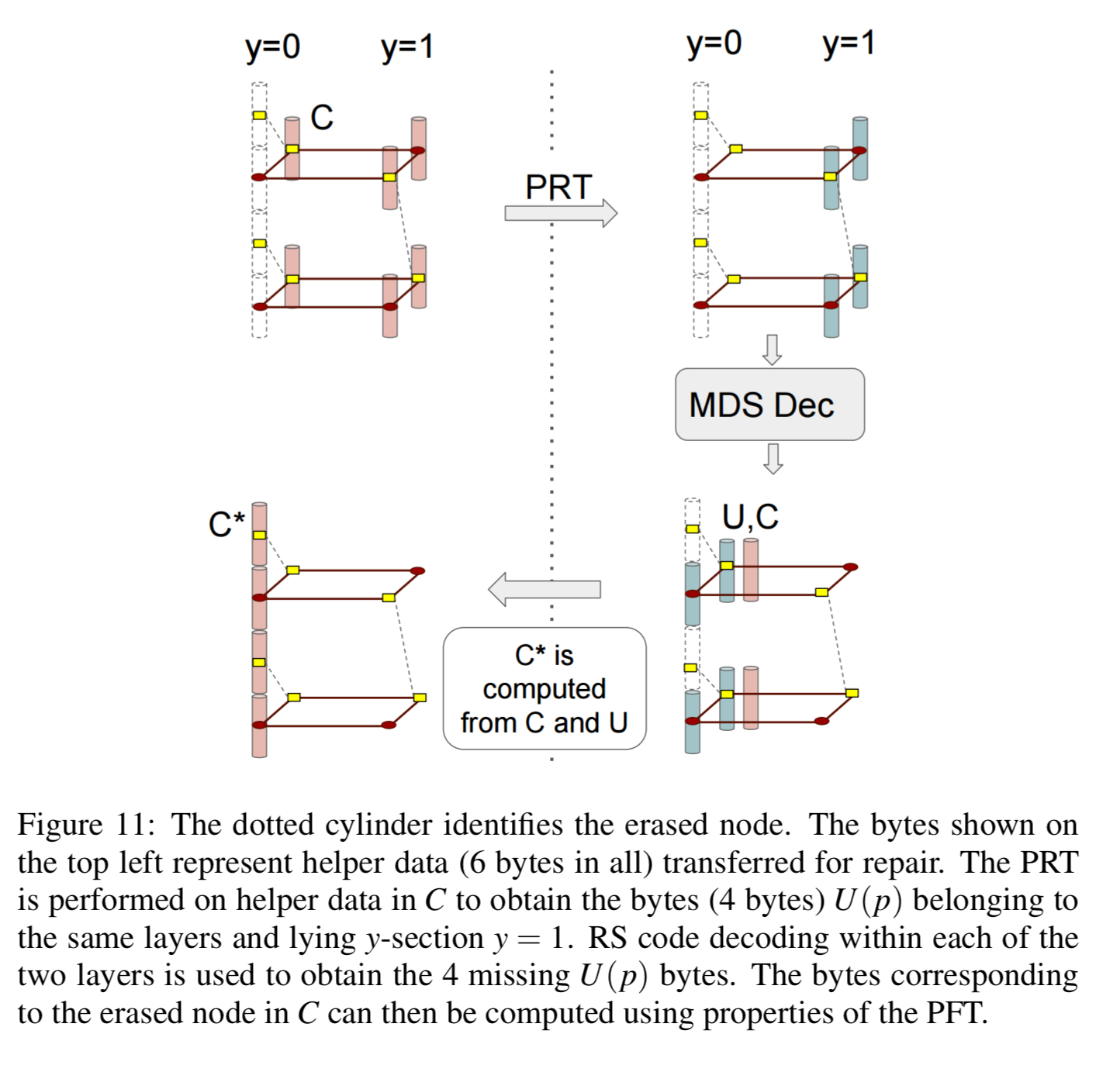
Suppose we now have a node failure, losing the dotted column in figure 9 below:
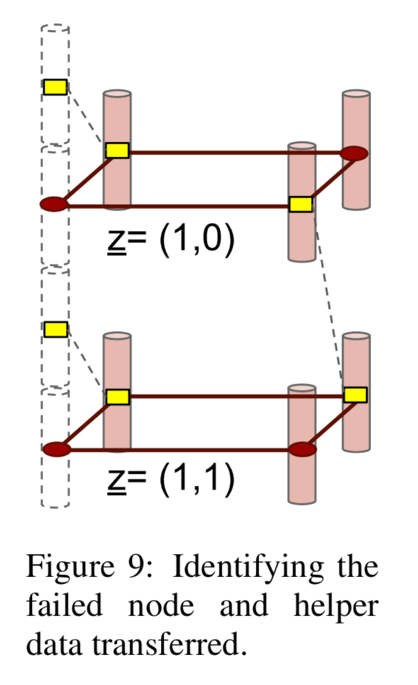
To repair the node, only the two layers z = (1,0) and z = (1,1) corresponding to the presence of the red dots within the dotted column are called upon for node repair. Thus each helper node contributes only 2 bytes, as opposed to 4 in an RS code, towards node repair and this explains the savings in repair bandwidth.
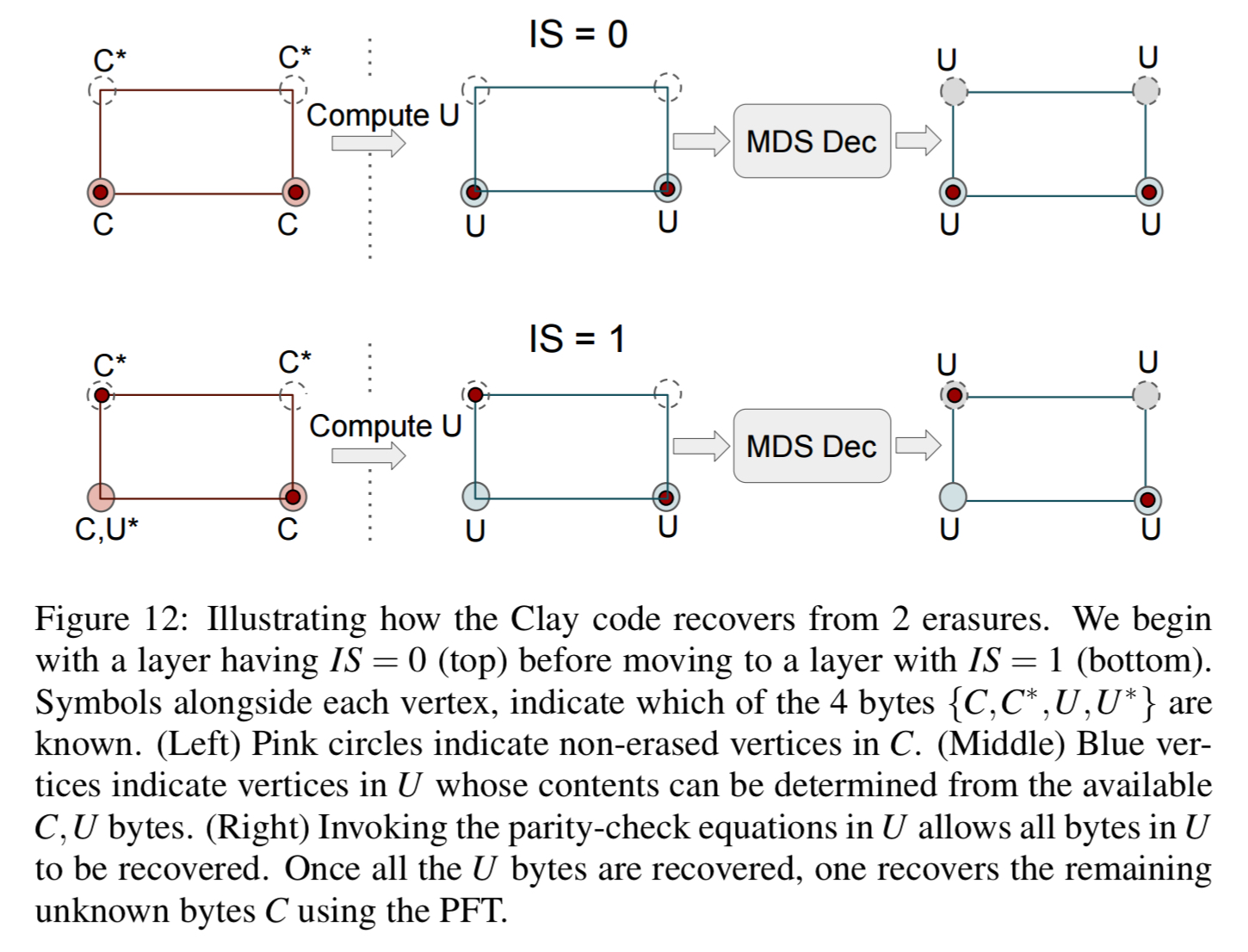
If there are multiple node failures (but no more than n-k), decoding can be carried out sequentially layer by layer to correct the erasure. Layers are processed in increasing order of the number of missing red dots within a layer. See the following figure for a succinct explanation.
The last word
Clay codes can be constructed via a simple two-step process where one first stacks in layers,
See the full paper for details of the implementation in Ceph and the experimental evaluation, which I didn’t have space to cover here.