Human-Robot Teaming for Rescue Missions: Team ViGIR’s Approach to the 2013 DARPA Robotics Challenge Trials – Kohlbrecher et al. 2014
Yesterday we looked at ROS, the Robot Operating System. Today I thought it would be fun to see an example of ROS in action, and where better to find that than in a DARPA Robotics Challenge! This paper gives an appreciation of the many dimensions involved in designing a robotics system, as well as further glimpses into the extensive set of OSS libraries that have grown up around the robotics research community and ROS.
The challenge:
In the spring of 2012, the United States Defense Advanced Projects Research Agency (DARPA) proposed the DARPA Robotics Challenge (DRC) to accelerate development and evaluation of disaster response robots that have the capability for early response and mitigation of disasters. This effort was partly motivated by the earthquake and tsunami that struck the Tohoku region of eastern Japan on March 11, 2011, and led to subsequent damage to the Fukushima Daiichi nuclear plant. The DRC is designed to mimic the tasks that might be required of a robot (Nagatani et al., 2013) to respond to the initial damage and avert subsequent catastrophes.
The DRC is designed to exercise the complementary strengths of the robot system and human operators. The robot can carry out plans and goals set by human operators in real time:
In our system, the robot is never fully autonomous and therefore has a low score for human independence(Huang et al., 2007). The human members of the team function as supervisors who set high level goals, teammates who assist the robot with perception tasks, and operators who directly change robot parameters to improve performance(Scholtz, 2003); as these roles change dynamically during a set task in our system, we will use the term operator generically. Following (Bruemmer et al., 2002), we rarely operate in teleoperation where we directly control a joint value, and primarily operate in shared mode where the operator specifies tasks or goal points, and the robot plans its motions to avoid obstacles and then executes the motion only when given permission. Even when executing a footstep plan in autonomous mode, the operator still has supervisory control of the robot and can command the robot to stop walking at any time, and safely revert to a standing posture.
Hardware
This is the point in a typical ‘The Morning Paper’ paper selection where the authors describe what EC2 instance types they used, and how many. In the world of robotics, you get this instead!
The system hardware is composed of three major sub-systems as shown in Fig. 1: the robot, the “onboard” computers, and the OCS hardware. Team ViGIR uses the Atlas robot that includes a robot control computer and Ethernet switch that handles communications with the sensors and robot hands. The “onboard” or “field” computers run the robot control and perception software developed by Team ViGIR. In the future, these field computers will be carried onboard the robot itself, but for ease of development leading up to the DRC Trials DARPA allowed these to be separate computers connected to the robot via a 10 GB/second fiber optic network connection. During the DRC Trials, the onboard computers were connected to the OCS computers via a 1 GB/second network connection that passed through a network traffic shaper; the traffic shaper introduced communication restrictions intended to mimic the effects of poor wireless communications. All operator interactions with the robot occurred through the OCS hardware, with commands sent to the onboard software via the traffic shaper connection.
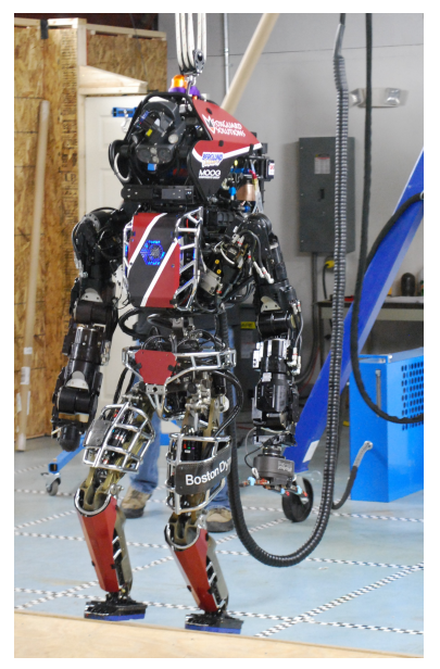
The Atlas robot itself is supplied by Boston Dynamics Inc. It’s a pretty cool piece of kit:
The Atlas system is a hydraulically actuated anthropomorphic robot developed by Boston Dynamics Inc. (BDI). The robot has 28 actuated degrees of freedom (DOF), stands 1.88m tall and weighs approximately 150kg. There are 6 DOF per arm and leg, 3 DOF for torso motion, and one DOF for head pitch motion. For the DRC Trials, the robot was used in a tethered configuration as shown in Fig. 1, with the tether providing electrical power, coolant flow, and a 10 gigabit Ethernet connection . The robot is equipped with a number of sensors. The main external sensor is a Carnegie Robotics MultisenseSL sensor mounted as the head. This sensor uses both a Hokuyo UTM-30LX-EW LIDAR mounted on a slip ring for continuous rotation and a stereo camera system that performs stereo disparity computation on a onboard FPGA. Both sensors are calibrated against each other using a calibration approach supplied by the manufacturer. Additionally, there are two situational awareness (SA) cameras mounted below the head with high field of view fisheye lenses. The robot provides a pose estimate based on an internal IMU and internal joint sensing.
The Challenges
Guided by its human operators, the robot must achieve eight tasks.
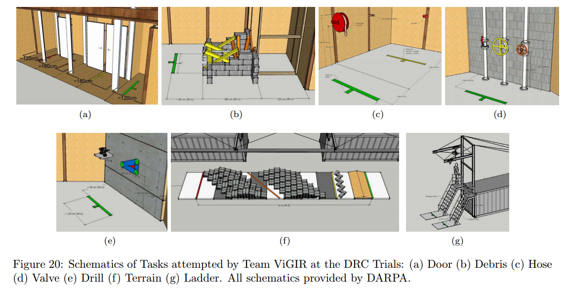
- Crossing through three different doors (a push, a pull, and a weighted pull)
- Removing debris from a doorway in order to walk through it
- Taking a hose and attaching it to a wye located several meters away
- Opening a series of lever and rotary valves
- Cutting a pattern out of a wall using a drill
- Driving a Polaris Ranger vehicle through a slalom course: “the robot could be placed into the vehicle at the start, but had to drive the length of the course to receive a single point. Two additional points were earned by having the robot climb out of the vehicle, and walk across the finish line. ” The ViGIR team did not attempt this challenge.
- Walking over a variety of terrains: a pitch ramp, a chevron hurdle, and a set of stairs
- Ascending a ladder to a raised platform.
Software Platform and use of ROS
Early on, the team chose to base the system software on the open source Robot Operating System (ROS)(Quigley et al., 2009) to take advantage of the available libraries and infrastructure. The system communications use ROS as the middleware, with two separate ROS networks being used during competition. One ROS network handles communications between the OCS computers, while the second ROS network handles communications on the onboard computers.
For the onboard system, the robot is modeled using the Unified Robot Description Format (URDF). URDF looks pretty ugly to me – the robotics folks could do with a nice modern DSL… :
Leveraging proven best practices within the ROS ecosystem, the robot is modeled using the URDF format and standard tools like the tf library are used to provide a basic robot setup and model that could directly be used by many higher level components, like the motion planning system. The robot model is constructed at runtime using the xacro macro toolset, to allow for flexibility (e.g. for choosing from available hand options on a per arm basis).
Many components of ROS are also used to build the operator control system:
Since we use ROS, we are able to take advantage of the several existing tools that it provides, mainly rviz and rqt. In the development of our main widgets (described in section 3.3), we use a combination of librviz, Qt, and Ogre. Leveraging the existing tools in librviz for visualizing 3D data communicated via ROS was very important given the short amount of time to implement the system before the DRC Trials. All 3D views in the OCS use existing and customized versions of rviz plugins (e.g., adding support to our own methods for picking geometry), in addition to completely new plugins that implement some of our OCS’ unique features (e.g., templates). For the development of simple 2D widgets, we use rqt extensively; this allowed us to quickly prototype widgets during development that act as windows for specific controllers on the onboard side (e.g., footstep controller parameters).
In the competition environment, teams must assume patchy communication between the robot and the operations center. ROS it turns out, is not partition tolerant!
As stated above our team chose to use ROS for our communications middleware. The ROS system uses a publisher/subscriber model with a centralized roscore to coordinate communications between ROS nodes. This is not suitable for use with the communications challenges defined above as the system cannot tolerate loss of communications to the centralized roscore. For this reason, the team chose to use two separate ROS networks for the onboard and OCS software and develop a custom communications bridge (CommsBridge); this setup was used during the initial VRC and throughout the DRC Trials.
Major Systems
Let’s take a look at some of the major systems that needed to be developed / integrated in order to get a feel for what such projects involve and what software support there is for building them.
Perception
For perception we need to build a world model.
The Worldmodel Server component preprocesses, collects and aggregates sensor data and makes it available to both onboard and OCS system components. Leveraging established open source tools like Point Cloud Library (PCL) (Rusu and Cousins, 2011) and Octomap (Hornung et al., 2013), the worldmodel server allows queries of information about the environment with flexible level of detail and bandwidth consumption.
Onboard the robot, LIDAR data is used for constructing a 3D geometry model of the environment. The dataflow pipeline is as follows:
First, scan data is filtered for spurious measurements commonly called shadow points or mixed pixels that occur at depth discontinuities (Tuley et al., 2005) using the shadow point filter available for ROS. The filtered scan is then converted to a point cloud representation. During this process, the rotational motion of the LIDAR on the slip ring is considered and high fidelity projection is employed, transforming every scan endpoint separately. In a last step, parts belonging to the robot have to be filtered out of LIDAR data. To increase robustness against errors in kinematics calibration, a specialized robot geometry model uses simplified and enlarged collision geometries for self filtering purposes. LIDAR scans are saved to a ring buffer along with snapshots of coordinate frames used within the system. By employing this method, aggregate point clouds relative to different coordinate frames can be provided on request.
The primary 3D model is then created using Octomap, “a volumetric, probabilistic approach using an octree as a backend.”
For the challenge, the team used a library of pre-defined templates for the objects they knew they were likely to encounter. The operator inserts these templates into the 3D representation of the environment as appropriate. Work was also begun on an automatic object recognition system:
An automatic object detection and pose estimation system using the Object Recognition Kitchen (ORK) framework as a backend and adapting the LINEMOD (Hinterstoisser et al., 2011) approach for DRC tasks
has been developed within the team. This was not used during the DRC Trials due to time constraints
and challenges in adjusting the system to work under outside light conditions. We intend to further explore automatic pose estimation during the next phase.
Motion Control
Although the use of hydraulics in heavy machinery is quite common, there are relatively few examples of hydraulically actuated humanoid robot systems in comparison to the large number of electrically actuated robots used both for research and in commercial applications. While advantageous in terms of bandwidth and force magnitudes that can be generated, hydraulic actuation poses significant challenges for control of the Atlas robot system. Given limited development time, Team ViGIR chose to focus on position/velocity based joint control techniques using the BDI (Boston Dynamics, Inc.) interface.
The joint control API permits control over position, velocity, and force using a proportional-integral-derivative (PID) based control law with some feed-forward terms. “We predominantly used position-based PD control with a force term used for gravity compensation and a feed-forward term based on commanded velocity.” So there.
Motion Planning
This involves two main areas: planning where the robot should put its feet, and planning how to move the robot’s manipulators (‘hands’) into position ready to perform some task.
Footstep planning it turns out, is a thing. And it’s supported by a ROS package:
As described in Section 5.2 the Boston Dynamics API provides the capability for the robot to follow footsteps. Given a sequence of footsteps it generates and executes smooth trajectories for each foot placement which allows to decouple planning and execution level, also known as contacts-before-motion planning. For this purpose our approach is based on the already existing footstep planner ROS package
which expands a graph and applies an Anytime Repairing A* (ARA*) search algorithm to obtain a sequence of footsteps (Hornung et al., 2012). For 3D planning on rough terrain, a suitable 3D world model, as well as suitable states, actions, transitions, and cost functions must be defined.
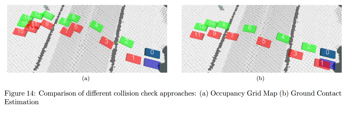
The footstep planning has to minimize multiple competings costs: for example, shortest path and risk of falling. Sometimes the robot has to step on top of obstacles, resulting in less than 100% ground contact. I’m going to quote the passage describing this, mostly so that you I can show you ‘figure 14,’ which really brings the ideas to life:
The Atlas robot is not capable of stepping over a cinder block sized obstacle, so this task can be solved
only by stepping on top of such obstacles. For ground contact estimation, edge detection based on grid
maps generated from point cloud data was implemented first. While performing as expected, occupancy grid maps have the drawback of wasting space by encircling each obstacle with non-traversable cells. As a result, collision checks with occupancy grid maps are too strict because they enforce placing each foot avoiding obstacles completely. This results in longer paths and the ARA*-planner takes longer computational time trying to minimize this path length. The resulting plan in figure 14a is obviously an ineffective solution to travel across the pitch ramp. An alternative approach therefore estimates the percentage of ground contact for a given foot configuration which allows usage of foot configurations with less than 100% ground contact. The planner is thus capable of planning for overhanging steps while keeping them collision free without the usage of discretized occupancy grid maps, improving the result on the pitch ramp significantly (see figure 14b).
When getting ready to manipulate items, the robot has to be positioned in such a way that it can reach them. Key to this is selecting the appropriate pose for the robot pelvis: “For this, the Simox open source inverse reachability approach described in (Vahrenkamp et al., 2013) has been integrated with our system.”
We developed a custom manipulation planning package based on the MoveIt! (Chitta et al., 2012) framework available for ROS by using the low level MoveIt! API to provide additional specialized functionality required for the Atlas robot and DRC tasks. The system enables planning to goal joint configurations and to goal end effector poses. Two planning modes are available: The default mode is unconstrained planning, with joints free to move to reach the goal. Optionally, motion can be constrained to follow a Cartesian path between the start and goal end effector pose. In this case, waypoints are generated based on linear interpolation between start and goal position and orientations for waypoints are generated using spherical linear interpolation (Slerp) (Shoemake, 1985) between start and goal end effector quaternions. More complex constrained motions such as circular motion for turning a valve are generated by concatenating multiple short linearly interpolated Cartesian paths.
Grasping
All of the objects in the DRC Trials competition were well defined; therefore, we chose to create a 3D geometry template for all relevant objects, matching sizes and shapes. Each template contains information related to the object such as mass, center of gravity, and nominal orientation. Grasps are created off-line using the GraspIt! toolkit (Miller and Allen, 2004), taking into account parameters such as hand type, task, object size and relative location of the object in the environment.
“Ghost robots” are used to test for reachability ahead of instructing the real robot:
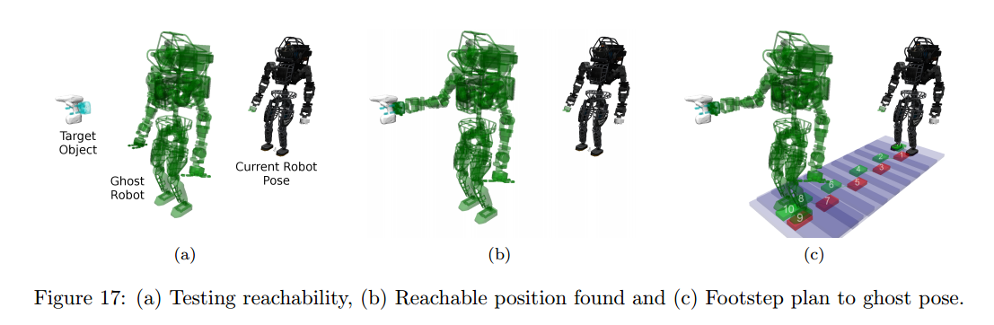
After placing the template and selecting the grasp, the grasp can then be tested for reachability using the ghost robot (Fig. 17a). If the grasp is reachable, the IK solution is displayed (Fig. 17b). If no solution is found, the ghost robot remains unchanged in its previous state. The user can then manipulate the robot pose, grasp orientation, template location, or torso constraints until the desired grasp is achievable. Once a feasible configuration is found, the user can send a footstep plan to move the real robot to the ghost robot pose. (Fig. 17c).
Open Source Robotics Tools/Projects
Here are convenient links to all of the open source robotics tools and libraries mentioned in the paper:
The Open Source Robotics Foundation sponsors both ROS and the Gazebo robot simulator.